The design of any communication link is based on. Tranzeo Wireless Technologies Inc.
![]()
Link Budget Ppt Download
Link Design Process 1.

. Effective isotropic radiated power. EC8652 WC Notes. Meeting of minimum CN ratio for a specific percentage of time.
One example involves a short range wireless link capable of 40kbitss kbps which might be suitable to provide a laptop computer with wireless access to a nearby dial-up modem. This discussion is followed by two simple examples. A link budget is used to compute cell coverage by accounting for all the factors that determine the cell coverage to balance the system cost against the required cell capacity.
Based on the SNR we can derive the RF receiver budget using heuristics and well known link budget analysis techniques. What is link budget. Anna University Regulation 2017 ECE EC8652 WC Notes WIRELESS COMMUNICATION Lecture Handwritten Notes for all 5 units are provided below.
All students must attend all presentations during the week of 3-7 May. Both push-to-talk communication device. Range How much transmission power do you need.
2011 Powerpoint slides due Saturday Apr 30 by 5pm. Yimin Zhang Villanova University 3 ECE 8708 Wireless Communications. Link Budgets CN ratio calculation is simplified by the use of link budgets Evaluation the received power and noise power in radio link.
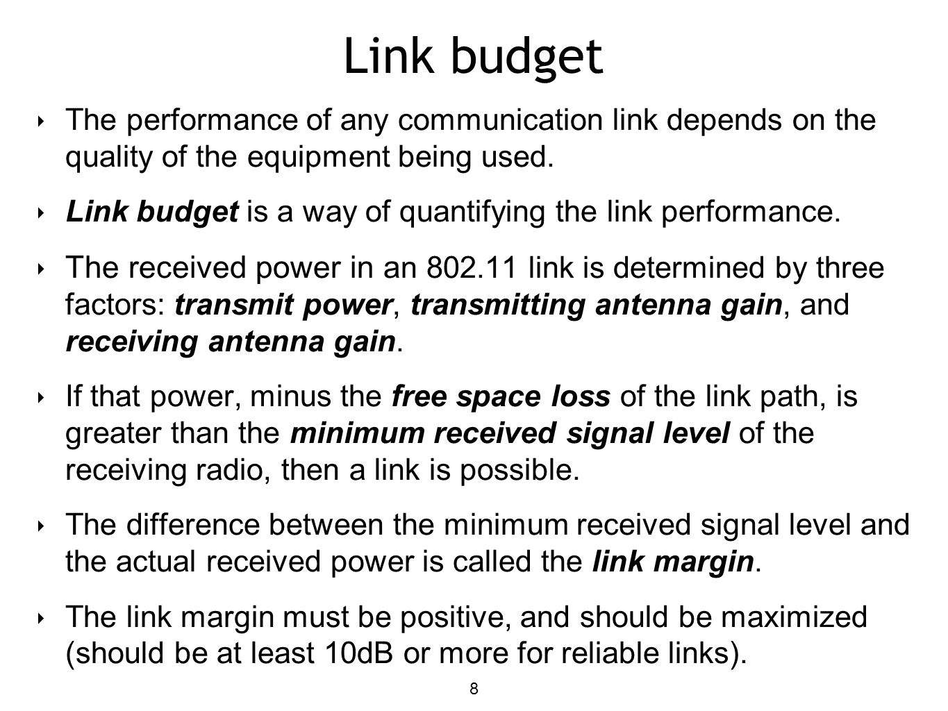
Link budget is a way of quantifying the link performance. Accounting all losses and gains from the transmitter the medium to the receiver. There will not be any extensions allowed.
Link Budget Analysis of an 80211b System The occupied bandwidth of an 80211b spread spectrum system is 22 MHzEach bit is spread over 11 chips. The link budget must be calculated for individual transponder and for each link When a bent pipe transponder is used the uplink and down link CN rations must be combined to give an overall CN Satellite Link Design Downlink received Power. 6044606005 Toll Free.
There is a minimum required associated with the minimum required service quality. The second example involves a high speed 2Mbps longer range link designed for Wireless. Carrying the maximum revenue earning traffic at minimum cost.
The received power in an wireless link is determined by three factors. Practical Link Budget Design. As a wireless network engineer you are often required to perform link budget calculations for such Microwave links.
Transmit power transmitting antenna gain and receiving antenna gain. Factors that cannot be controlled directly but. The transmitter and receiver antenna gains including connector and VSWR losses are 05 dBi.
After returning from war veterans had the expectation that wireless communications should be available in their civilian jobs 19. Mathematically it can be written as E I R P G P s We can represent EIRP in decibels as E I R P G P s d B W Where G is the Gain of Transmitting antenna and P s is the power of transmitter. SlideShare uses cookies to improve functionality and performance and to provide you with relevant advertising.
Design Each Link Select frequency Select modulation coding Apply antenna size beam width constraints Estimate atmospheric rain attenuation Estimate received noise interference power Calculate required antenna gain transmitter power 3. Class is cancled for today 28 Apr. Microwave Link Budget Design 10 Microwave communication is commonly used as a backbone transmission system in wireless communication networks.
How much you can spend on the channel loss. Propagation Large-Scale Path Loss Mobile Radio Propagation Mobile radio channel is an important controlling factor in wireless communication systems. -Written Project Reports are due by electronic transmission and in paper format by 5pm Thursday April 28 2011.
AP to Client link 12 20 dBm TX Power AP 10 dBi Antenna Gain AP - 2 dB Cable Losses AP 14 dBi Antenna Gain Client - 2 dB Cable Losses Client 40 dB Total Gain -114 dB free space loss 5 km -73 dBm expected received signal level --82 dBm sensitivity of Client 8 dB link margin 13. LINK BUDGETLINK BUDGET PERFORMANCEPERFORMANCE characteristics of TX station RX station propagation noise interference characteristics of sa 1 66. The systems noise figure is assumed to be 7 dBThe required E b N o to achieve a BER of 10 6 is 11 dB.
But the phone sytem the Public Switched Telephone Network PTSN was. In this case for a power sensitivity of -100 dBm and a 10-bit ADC with 0 dBm of saturation power the RF receivers specification is of 51 dB of gain and 11 dB of noise figure. Link budget factors controlled by the RF engineer include transmitter-radiated power antenna gain noise figures and co-channel interference ie reuse factor N.
ECE 8708 Wireless Communications. One such link is shown below in Figure 1 which operates in the 20 GHz radio. Download link for ECE 6th Sem WIRELESS COMMUNICATION Notes are listed down for students to make perfect utilization and score maximum marks with our study materials.
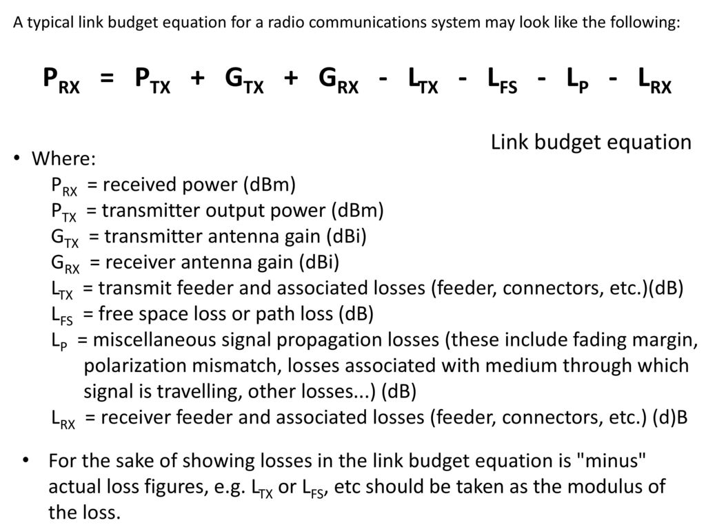
The purpose of calculating link budget is to investigate the system performance tied to operation threshold to get the minimum power cmin that should be received at the demodulator input in order for communication to work properly with reading typically of 10 dbby using this design all the parameter ie. Link budget calculations are an essential step in the design of a radio communications system. The link budget calculation enables the losses and gains to be seen and devising a link budget enables the apportionment of losses gains and power levels to be made if changes need to be made to enable the radio communications system to meet its operational requirements.
Equivalent isotropic radiated power EIRP is the main parameter that is used in measurement of link budget. Therefore the word budget. If that power minus the free space loss of the link path is greater than the minimum received signal level of the receiving radio.
Basic link budget analysis. Client to AP link 14 Link Budget margin Net Gain Receiver sensitivity The receiver sensitivity at the AP receiver is given as-89dBm Net Gain Gains losses Gains 15 dBm TX Power Client 14 dBi Antenna Gain Client 10 dBi Antenna Gain AP 39 Losses 2 dB Cable Losses Client 2 dB Cable Losses AP 114 dB free space loss 5 km 118 Net. Define Requirements for each link 2.
Propagation Large-Scale Path Loss. 19473 Fraser Way Pitt Meadows BC Canada V3Y 2V4 T. From the link and power budget calculations the CubeSat antenna must achieve a minimum gain of 7 and 5 dBi at 8 and 112 GHz respectively to cover a.
Easy Steps to a Good Link Power Budget First draw a sketch of the link path Doesnt have to be artistic quality Helps you find the stuff you might forget Next think carefully about the system of interest Include all significant effects in the link power budget Note and justify which common effects are insignificant here Roll-up large sections of the link power budget Ie. Link-power budget calculations take into account all the gains and losses from the transmitter through the propagation medium to the receiver in a.
Link Budget Ppt Download

3 9 Predictable Link Budget Design Using Path Loss Models Ppt Video Online Download

Link Budget Ppt Download
Ppt Link Budget Powerpoint Presentation Free Download Id 3282925

Link Budget Calculation Ppt Video Online Download

Link Budget Calculation
Link Budget Calculation Ppt Video Online Download
Link Budget Ppt Download
0 comments
Post a Comment